
PCB Material Selection Guide
The right Printed Circuit Board (PCB) material is the one that meets the electrical, thermal, mechanical, and manufacturing needs of the finished product without adding unnecessary complexity or cost. That decision extends beyond a material datasheet. It influences fabrication, assembly, testing, and long-term reliability.
Properties such as dielectric constant (Dk), dissipation factor (Df), glass transition temperature (Tg), and coefficient of thermal expansion (CTE) all play a role, but no single value determines the best choice. The application, operating environment, and manufacturing process must be evaluated together. Understanding how these factors work together helps engineers select materials that support both product performance and efficient manufacturing.
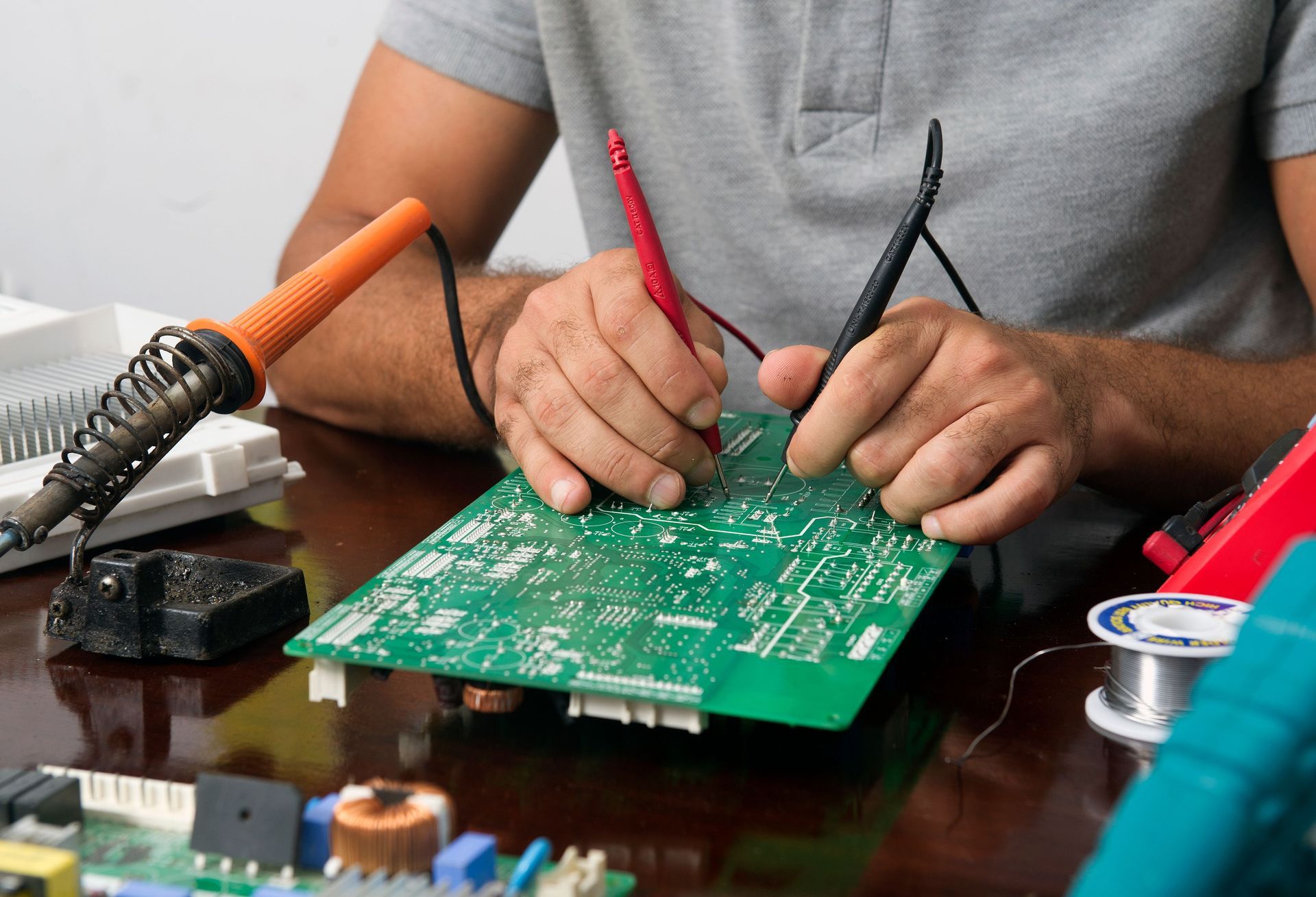
Why PCB Material Selection Matters
PCB material selection influences far more than the bare board. The chosen laminate affects signal integrity, heat dissipation, dimensional stability, manufacturability, and long-term reliability. Selecting a material that exceeds the application's needs can increase cost and sourcing complexity, while selecting one that falls short may contribute to performance issues, production delays, or a shorter product lifespan. The best choice balances electrical, thermal, mechanical, and manufacturing requirements instead of optimizing for a single property.
Because those tradeoffs extend beyond circuit design, material selection works best as an early engineering decision. Reviewing the application alongside the PCB layout helps identify potential constraints before fabrication and assembly begin. Bringing design and manufacturing considerations together early reduces redesigns, supports smoother production, and creates a stronger foundation for evaluating the material properties discussed next.
Key Properties to Evaluate in PCB Materials
No single property determines the best laminate for every application. Their importance depends on the circuit's electrical performance, operating environment, manufacturing process, and reliability goals. Engineers typically evaluate these properties together.
| Property | Why It Matters |
|---|---|
| Dielectric Constant (Dk) | Influences signal speed and controlled impedance. Stable Dk is more important in high-speed and RF designs. |
| Dissipation Factor (Df) | Measures how much signal energy is lost in the material. Lower Df helps reduce insertion loss. |
| Glass Transition Temperature (Tg) | Identifies when the laminate begins changing from a rigid to a softer state, affecting thermal performance during assembly. |
| Coefficient of Thermal Expansion (CTE) | Measures how much the material expands with temperature changes. Lower CTE helps reduce stress on plated through-holes and vias. |
These properties should be evaluated together. Other characteristics, including thermal conductivity, moisture absorption, and mechanical strength, may also influence material selection.
Common PCB Material Types and Their Applications
PCB materials are available in several families, each suited to different applications. Selecting the right option starts with matching the material's properties to the product's performance and manufacturing needs.
| Material Type | Common Applications |
|---|---|
| FR-4 material | General-purpose electronics and industrial products requiring balanced performance and cost. |
| High-Tg FR-4 | Multilayer boards and assemblies exposed to higher operating or processing temperatures. |
| Polyimide | Flexible circuits, rigid-flex designs, and elevated-temperature applications. |
| RF and microwave laminates | High-frequency communication, radar, satellite, and other designs need stable electrical performance. |
| Metal-core materials | LED lighting, power electronics, and applications where heat dissipation is a priority. |
PCB color options are determined primarily by the solder mask rather than the laminate. Material selection should focus on electrical, thermal, and mechanical performance instead of appearance.
Matching PCB Materials to Electrical and Thermal Requirements
Selecting the right laminate starts with the circuit's operating conditions rather than the material itself. High-speed and RF designs often place greater emphasis on stable dielectric properties and low signal loss, while power electronics may prioritize heat dissipation and thermal stability. Operating temperature, power density, signal frequency, board thickness, and expected service life all help determine which material family is the best fit.
Thermal management also extends beyond the laminate. Copper weight, board construction, thermal vias, and component placement all influence how heat moves through a design. Comparing
aluminum vs. copper PCBs can also help when heat dissipation is a primary concern, as each construction offers distinct advantages. Evaluating electrical and thermal requirements together helps teams select a material that meets performance goals without creating unnecessary manufacturing complexity.
PCB Material Considerations for High-Reliability Industries
Material selection takes on added importance when products operate in demanding environments or have limited tolerance for failure. Applications in medical, military, and aviation and aerospace sectors often experience temperature extremes, vibration, repeated thermal cycling, or extended service lives. Those conditions may favor materials with greater thermal stability, lower expansion rates, or more consistent electrical performance, depending on the application's operating requirements.
Regulatory and quality expectations also influence material decisions. Depending on the application, factors such as traceability, documentation, and
RoHS compliance may become part of the review alongside electrical and thermal performance. Bringing engineering and manufacturing teams together early helps identify potential risks before fabrication begins and supports more consistent production throughout the product lifecycle.
How Material Selection Affects PCB Fabrication and Assembly
PCB material influences much more than circuit performance. Different laminates can affect drilling, plating, lamination, dimensional stability, and the way a board responds to soldering temperatures. Some materials also require specialized fabrication processes or tighter process controls, making it important to confirm manufacturing compatibility before production begins.
Those decisions continue into assembly. Material properties can influence reflow performance, rework, inspection, conformal coating, and long-term reliability after components are installed. They may also affect downstream manufacturing steps, including
box-build assemblies, where completed circuit boards are integrated into the final product. Reviewing material selection early helps identify manufacturing constraints, align fabrication and assembly processes, and reduce the likelihood of production delays or quality issues.
Reducing Risk Through Early Material and Manufacturing Review

The most effective material decisions happen before fabrication begins. Reviewing application requirements, manufacturing processes, and PCB layout early helps identify potential issues while design changes remain easier and less expensive to implement. An early design for manufacturability (DFM) review can also identify production constraints before fabrication begins. This collaborative approach reduces redesigns, supports smoother production, and increases confidence that the selected material aligns with the product's electrical, thermal, and mechanical requirements.
At
EI Microcircuits, we help customers evaluate material choices alongside manufacturing considerations early in the design process to identify potential production challenges before they affect schedules or performance. If you're planning a new project or refining an existing design,
contact us to discuss your manufacturing goals and determine the best path to reliable production.
let's talk
EI Microcircuits is comprised of three production facilities totaling over 100,000 square feet of climate-controlled manufacturing, engineering and warehousing. We are ready to be the solution to your next project. Contact Us, Request a Quote or Schedule a Tour today!
Manufacturing plant 1
1651 Pohl Road
Mankato, MN 56001
P: 507.345.5786
Manufacturing plant 2
2011 Klein Street
St. Peter, MN 56082
P: 507.934.5722
manufacturing plant 3
69 Power Drive
Mankato, MN 56001
P: 507.386.9160
*Each facility is configured to support your production needs. While maintaining continuity with each other in equipment, training and process control, each facility offers its own specialty. All facilities share the same data center to allow for seamless manufacturing between locations.