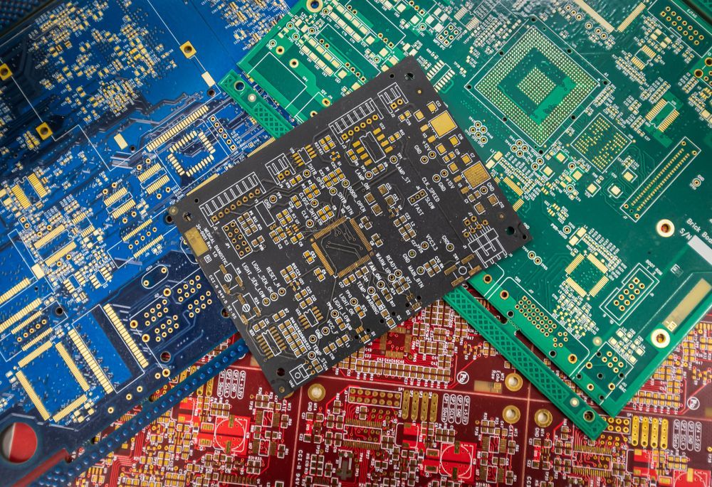
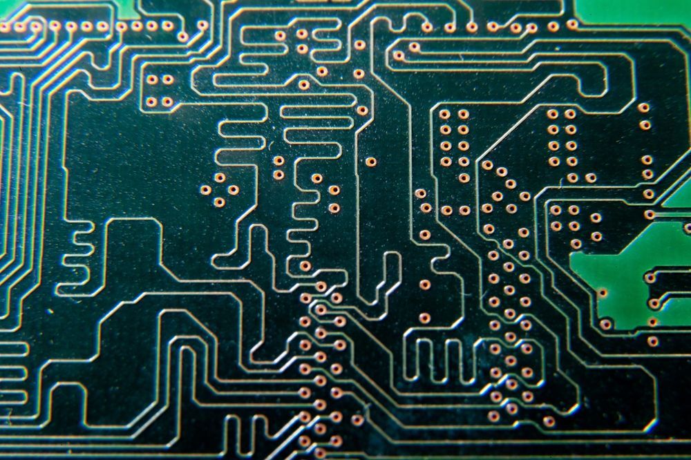
What color can you make your PCB?

February 27, 2026

Share this article:

Printed circuit boards are often associated with a familiar green surface that has become almost synonymous with electronics. Today’s fabrication processes, however, offer far more color options. For OEM teams building high‑reliability products, color is a practical decision linked to inspection, compliance, and long‑term manufacturability.


The color of a
PCB is seldom a purely cosmetic choice. It connects to process control, regulatory alignment, and lifecycle planning.

Circuit boards in blue, green, red, and black, displaying intricate electrical pathways and components.

What Determines PCB Color?

PCB color is defined by the solder mask applied during fabrication. The base laminate, typically FR‑4, remains consistent, while the pigmented epoxy solder mask creates the visible surface. The mask protects copper traces, reduces solder bridging, and contributes to insulation resistance.


Color choice is closely tied to
how PCBs are built, including curing profiles, material chemistry, and compatibility with inspection systems. Fabricators qualify specific pigments and solder mask formulations to meet IPC standards for adhesion, thickness, and durability across production volumes.

Standard PCB Solder Mask Colors

Common solder mask colors include:

  • Green

    Green circuit board with white lines and copper circles.

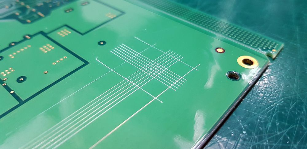
    Industry standard with strong contrast for inspection and stable behavior in high‑volume production. 
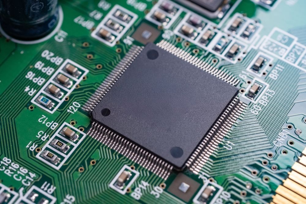
  • Black

    Close-up of a circuit board with a central microchip and various electronic components in shades of brown and gray.

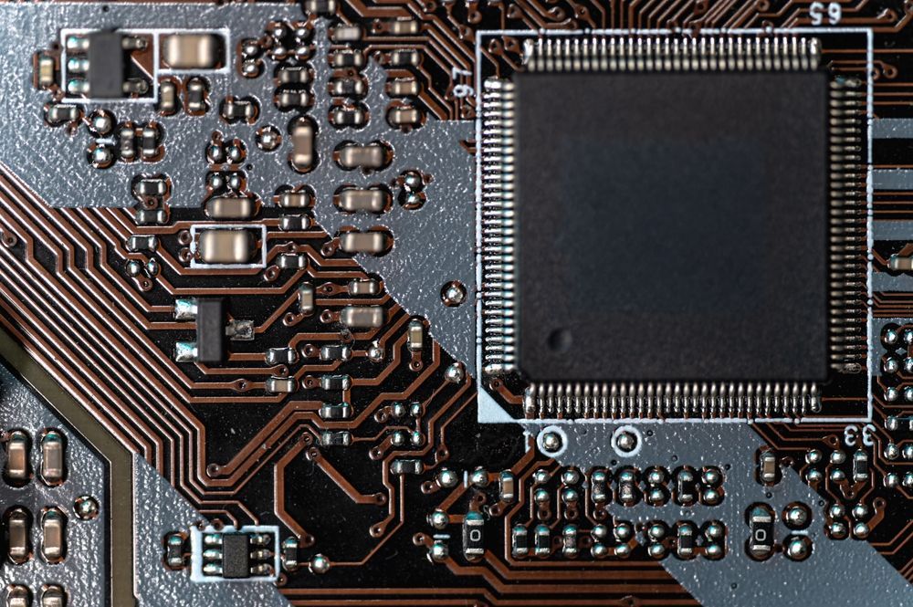
    Often selected for aesthetics, though it can reduce visual contrast during inspection. 

  • Blue

    Blue circuit board with intricate pathways and components.

    Good contrast with silkscreen and frequently used for product differentiation. 

  • Red

    Red circuit board with gold-colored traces and components.

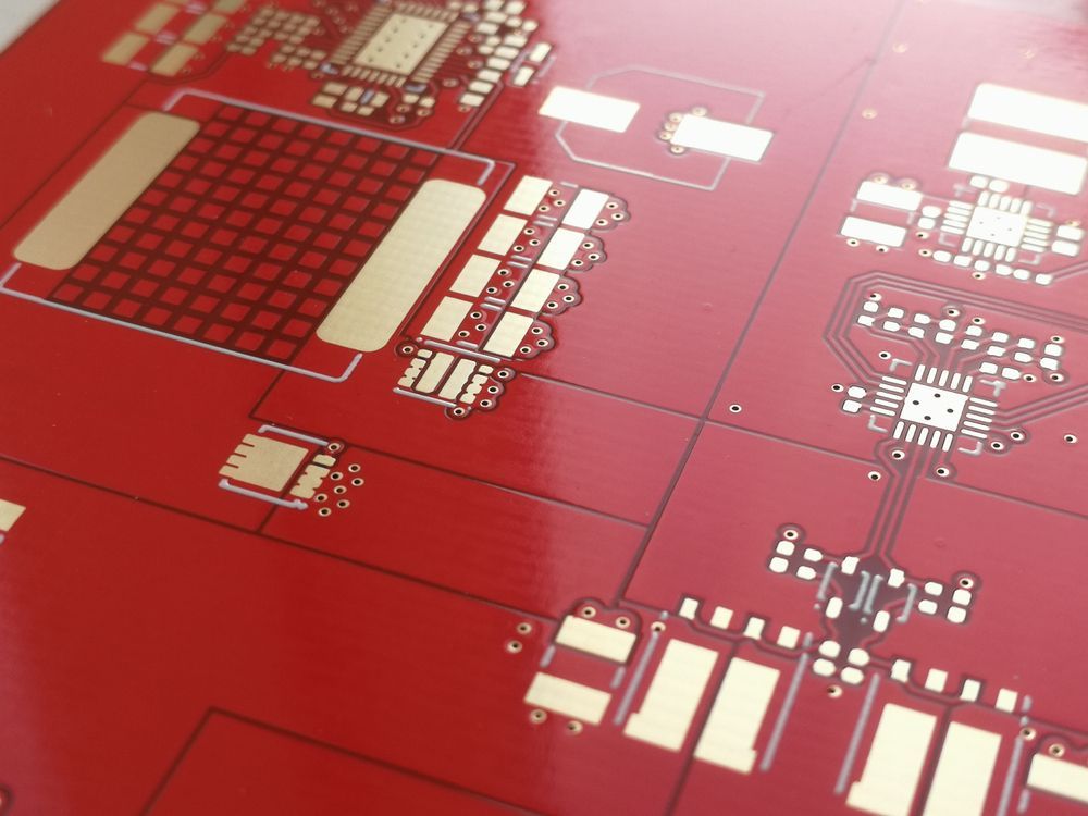
    High visibility that can be helpful in certain prototype environments. 

  • White

    Sheet with many small, repeating patterns of black geometric shapes on a silver surface.

    Common in LED applications due to its reflective surface properties. 

  • Yellow and Matte Finishes

    Close-up of a printed circuit board with yellow and gold electrical pathways and components.

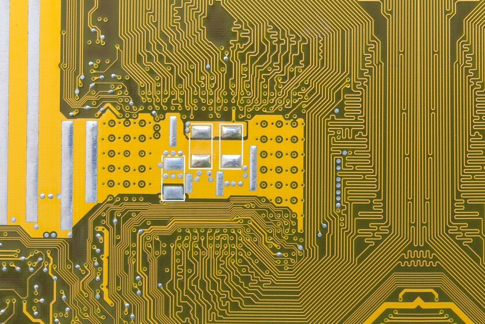
    Typically chosen for specialty builds or branding alignment.

Color availability depends on fabricator qualification, material sourcing, process control, validated curing parameters, and documented process capability limits.

How PCB Color Affects Inspection and Quality Control

Solder mask color influences inspection efficiency and defect detection. Automated Optical Inspection (AOI) systems rely on contrast between copper pads, solder joints, and the mask surface. Green remains popular because it supports clear visual differentiation under standard lighting. Black and other dark tones can reduce glare but may limit contrast in some inspection environments. White may introduce reflection challenges during AOI calibration and operator visual checks.


Any color choice should fit the inspection methodology, IPC acceptance criteria, and documented quality control procedures.

Performance Implications of PCB Color

In most designs, the solder mask shade has little impact on electrical performance. Solder mask thickness and dielectric properties stay similar across qualified pigment systems. Thermal behavior and light reflectivity, however, can matter in specific applications.


White masks often appear in LED assemblies to increase light output efficiency through higher reflectivity. Darker colors can absorb more radiant heat in high‑temperature environments, so they should be evaluated during material validation. This includes application‑specific testing under defined operating loads, environmental exposure conditions, long‑term reliability qualification, and accelerated life testing.

Regulatory and Industry Considerations

In regulated industries, solder mask color selection needs to fit within documented quality management systems and traceability controls. Medical device programs under ISO 13485 typically document material specifications, including solder mask formulation and approved pigment sources. Aerospace and defense programs aligned with AS9100D and ITAR registration may add configuration management requirements linked to part numbers and revision control.


A change from an approved color can trigger requalification testing, documentation updates, customer notification, and formal change control board review.

PCB Color Selection in High-Reliability Industries

In high‑reliability sectors such as medical, aerospace, and defense, PCB color decisions extend beyond visual preference. Programs frequently operate under strict configuration control, where consistent materials support validation, traceability, and stable long‑term production. A color change can alter inspection calibration, documentation baselines, and customer approval cycles.


Engineering teams need to evaluate color selection within the broader manufacturing plan, reliability testing strategy, and product lifecycle expectations tied to mission performance, field serviceability, long‑term supplier continuity, documented risk management, and contractual compliance.

Custom PCB Colors: What OEMs Should Evaluate

When considering custom solder mask colors, OEM teams should review:

  • Material Qualification – Confirm pigment formulations meet IPC requirements for adhesion and thickness.
  • Inspection Impact – Check compatibility with AOI, X‑ray, and visual inspection criteria.
  • Volume Stability – Validate supplier consistency across forecasted production runs.
  • Financial Implications – Examine tooling, minimum order quantities, and the cost structure for custom PCBs.
  • Change Control – Map formal approval workflows within regulated programs.
  • Lead Time Effects – Look at sourcing timelines for specialty pigments and how they influence fabrication schedules.

Color decisions should align with manufacturability, traceability, and long‑term production plans.

PCB Fabrication and Assembly Considerations

Solder mask color choice connects directly to fabrication sequencing and assembly controls. Solder mask application, curing profiles, and surface finish compatibility need to match the chosen pigment system. During assembly, color can influence stencil alignment visibility, solder joint inspection, and how easily rework is identified.


Manufacturing teams should examine fabrication capability, assembly process validation, documented workmanship standards, operator training needs, and inspection calibration protocols before finalizing color specifications. This helps maintain consistent yield and repeatable quality across prototype and full‑scale production builds.

Integrating PCB Color Into Full Box-Build Programs

PCB color selection should be considered within the context of full product integration. In box‑build assemblies, visual alignment with enclosures, cable harnesses, labeling, and internal documentation can shape service workflows and configuration control. Color can also aid internal identification during final assembly and depot repair.


Engineering and operations teams should confirm that board‑level specifications integrate smoothly with mechanical assemblies, testing protocols, serialized product tracking, customer documentation packages, long‑term field maintenance procedures, and cross‑functional change management that supports sustained production continuity.

Lifecycle and Obsolescence Planning

Board color selection should be viewed through the lens of long‑term production forecasts and obsolescence management. Specialty pigments or limited‑run solder mask formulations can create sourcing constraints across extended product lifecycles. In regulated sectors, even minor material substitutions may trigger formal change control and requalification testing.


Procurement, engineering, and quality teams should align on approved material lists, alternate sources, documented risk mitigation plans, supplier communication practices, and long‑term inventory strategies to sustain production throughout the life of the program.

How EI Microcircuits Supports PCB Fabrication and Assembly Decisions

At EI Microcircuits, board color selection is treated as part of a disciplined manufacturing strategy. Through our electronic manufacturing services, we coordinate fabrication controls, inspection methods, and lifecycle planning within documented quality management systems such as ISO 13485 and AS9100D. Our teams review material specifications, confirm inspection compatibility, and ensure fit within full assembly programs and serialized configuration management systems.


If color choices intersect with broader manufacturing priorities,
contact us to discuss how we can align your program with stable, high‑reliability production outcomes.

Connect with us:

Blue electronic circuit board with intricate pathways and components.
February 23, 2026
Learn pcb conformal coating processes, materials, and inspection methods for high reliability electronics manufacturing from EI Microcircuits experts.
Close-up of a blue circuit board with white components and traces.
February 16, 2026
RoHS compliance in high-reliability PCBA explained, covering materials, process control, and regulatory demands with expertise from EI Microcircuits.
Blue close-up of a circuit board with intricate pathways and components.
February 9, 2026
Compare aluminum pcbs and copper boards, thermal performance, and manufacturing tradeoffs with high reliability insights from EI Microcircuits.

let's talk

EI Microcircuits is comprised of three production facilities totaling over 100,000 square feet of climate-controlled manufacturing, engineering and warehousing. We are ready to be the solution to your next project. Contact Us, Request a Quote or Schedule a Tour today!

Contact Us Today

Manufacturing plant 1

1651 Pohl Road
Mankato, MN 56001

P:
 507.345.5786

Manufacturing plant 2

2011 Klein Street
St. Peter, MN 56082

P:
 507.934.5722

manufacturing plant 3

69 Power Drive
Mankato, MN 56001

P: 507.386.9160

*Each facility is configured to support your production needs. While maintaining continuity with each other in equipment, training and process control, each facility offers its own specialty. All facilities share the same data center to allow for seamless manufacturing between locations.