PCB Troubleshooting Guidebook
Even well-designed PCBs can exhibit unexpected behavior during production or in the field. The assumption is that once assembled, a board should work consistently. But failures still occur. Some are obvious. Others are more difficult to detect. Identifying the source involves a structured process, combining inspection, testing, and system-level context to guide resolution.
Understanding the Failure Landscape
Troubleshooting a printed circuit board begins with recognizing what failure looks like across different use cases. Symptoms may vary, but patterns often point to underlying process or design factors.
Common Types of PCB Failures
Failures typically fall into mechanical, electrical, or environmental categories. These may include open circuits, shorted traces, lifted pads, cracked solder joints, or damaged vias. In many cases, physical damage is visible. But intermittent faults, such as thermal drift or signal instability, may only emerge under specific operating conditions or extended use.
High-Reliability vs. Commodity Failures: What’s at Stake
Commodity boards may tolerate minor inconsistencies, but high-reliability assemblies used in medical, defense, or aerospace cannot. A single failure may impact patient outcomes, mission performance, or system integrity. Understanding these differences shapes how engineers prioritize root cause analysis, material selection, and
PCB inspection protocols across different build requirements.
Visual and Non-Destructive Inspection Techniques
Early-stage troubleshooting typically begins without powering the board. These inspection methods help identify defects that cannot be detected through electrical testing and avoid introducing further damage.
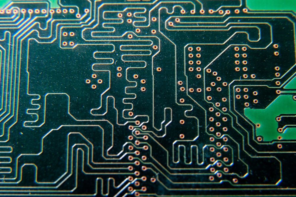
Automated Optical Inspection (AOI)
AOI uses cameras and pattern recognition to detect surface-level defects. It can identify missing components, solder bridges, skewed parts, and polarity issues. AOI works best in high-volume production where consistent placement and soldering are expected. While it cannot see beneath components, it quickly flags process deviations that may indicate broader systemic issues.
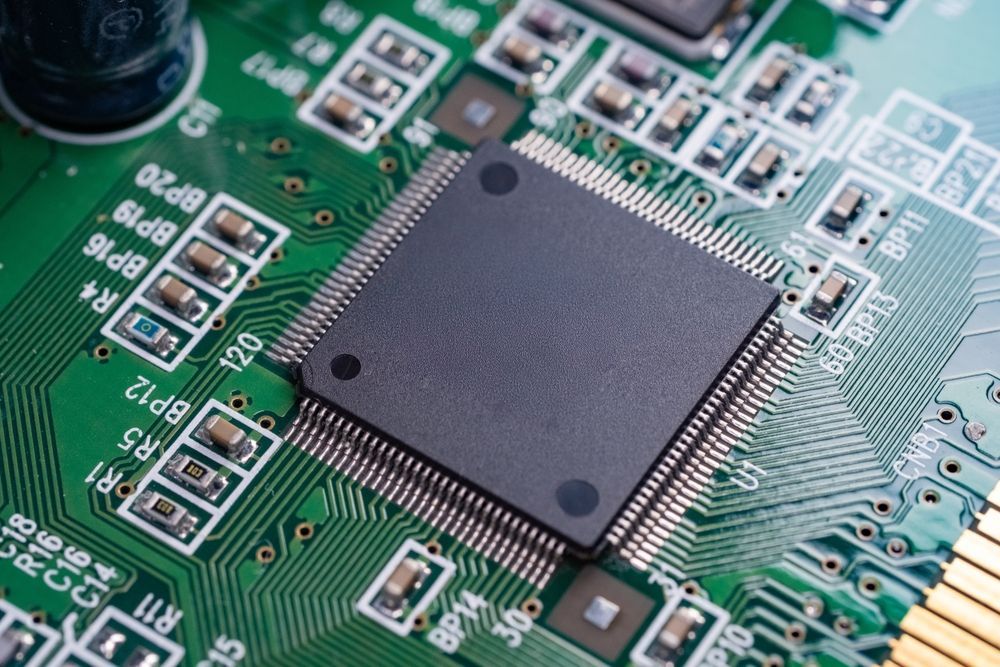
X-Ray Inspection for Hidden Defects
X-ray systems reveal defects beneath components like BGAs or inside multi-layer boards. This method is useful for spotting voids, insufficient solder, and misaligned pads where visual inspection fails. It plays a central role in diagnosing hidden electrical faults tied to complex package types and is especially relevant in high-density or miniaturized assemblies.
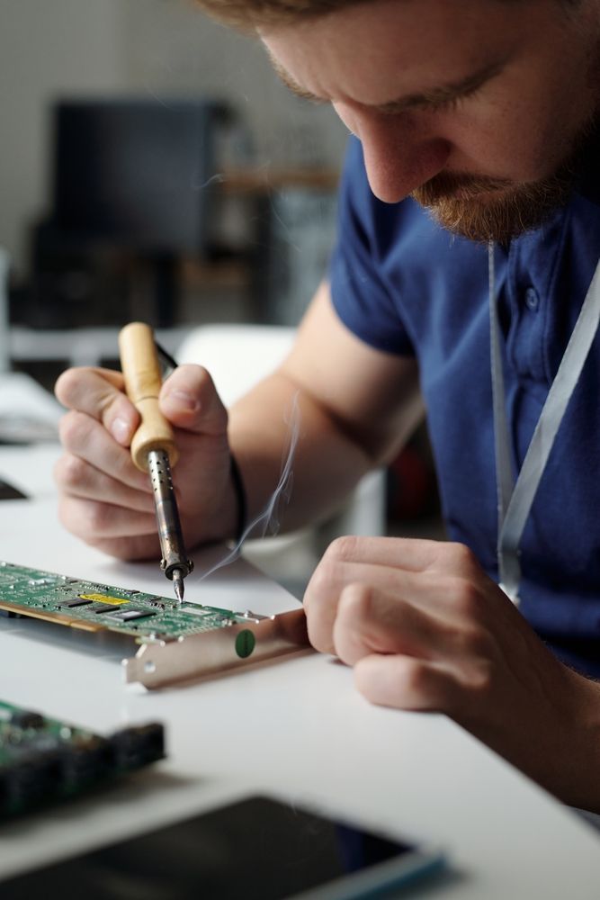
Manual Microscope Inspection
Microscope-based inspection allows operators to zoom in on specific areas for detailed examination. This is often used to check fine-pitch leads, rework sites, or solder joints that produce inconsistent results. Although time-intensive, manual inspection remains valuable for catching subtle mechanical or contamination-related issues that automation may overlook.
Conformal Coating Challenges and Clues
When boards are coated, troubleshooting becomes more complex. Conformal layers can obscure cracked joints or lifted components. However, defects like coating voids, bubbles, or discoloration often point to underlying problems. A flawed coating may result from improper cleaning, excess moisture, or an application process that needs further evaluation.
Functional and Electrical Testing Methods
Troubleshooting becomes more targeted when a board is powered. These methods evaluate circuit behavior under load and help pinpoint electrical issues tied to logic, power, or signal flow.
In-Circuit Testing (ICT)
ICT uses a bed-of-nails fixture or flying probe to measure resistance, capacitance, and connectivity at the component level. It identifies open pins, incorrect values, or misplacements before full system testing. ICT is fast and accurate but depends on access to test points, which may limit its use in densely packed or unconventional layouts.
Flying Probe Testing (FPT)
Flying probe systems test continuity, shorts, and basic functionality without a custom fixture. They are ideal for low- to medium-volume production or prototypes where test access is limited. The probes move freely across the board, adapting to different layouts. While slower than ICT, the flying probe adds flexibility and deeper reach during early fault isolation.
Functional Test (FCT) in End-Use Scenarios
Functional testing applies real-world operating conditions to verify that the assembly performs as intended. It confirms power behavior, signal flow, and logic function based on how the board will operate in its final system. FCT often requires custom fixtures or test software, but gives important validation for complex or safety-sensitive designs.
Power-On Behavior and Debug Strategies
Observing startup behavior typically reveals hidden faults. Symptoms such as overcurrent, undervoltage, or unstable signals can indicate regulator issues, ground faults, or damaged components. Using current-limited supplies, thermal cameras, or serial debuggers lets engineers isolate the issue without causing further damage. Controlled power-up becomes a key point in diagnosing persistent board-level problems.
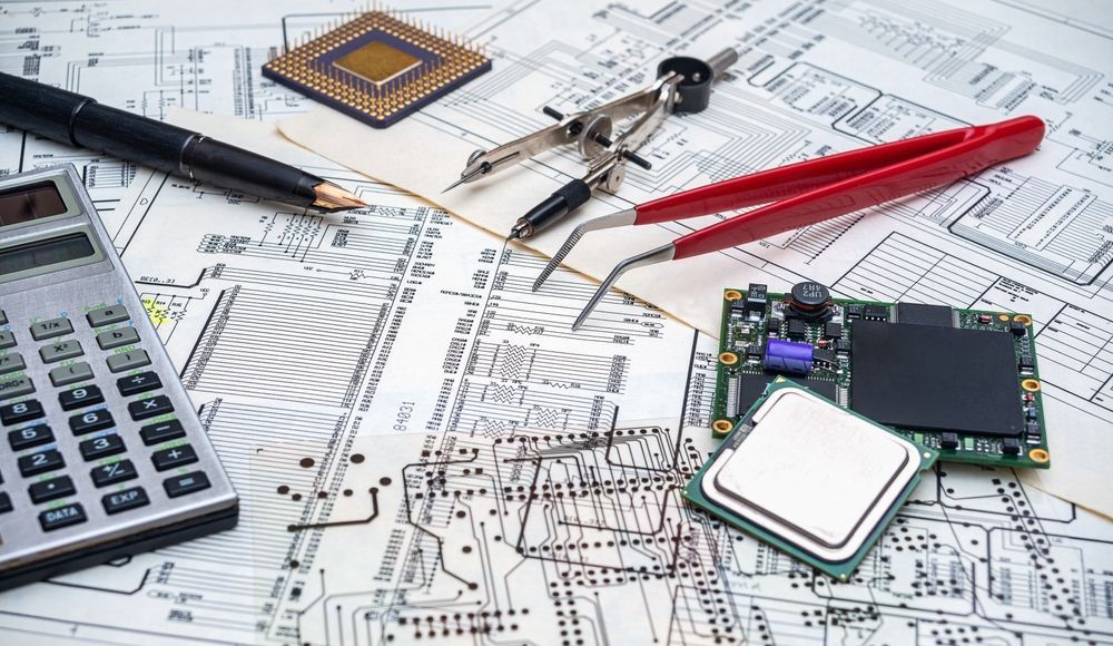
Root Cause Analysis and Diagnostic Tools
Pinpointing failure takes more than surface-level symptoms. Root cause analysis links observed behavior to underlying mechanisms, whether material-related, thermal, or process-driven. Tools like oscilloscopes, logic analyzers, and time-domain reflectometers help isolate signal integrity issues or timing faults.
Automated test development for PCBs adds another layer of insight by validating circuit response through repeatable, scalable scenarios.
Process-Based Troubleshooting
Failures frequently stem from upstream issues in soldering, cleaning, or handling. Reviewing process data such as reflow profiles, paste deposition, and placement logs can highlight inconsistencies that weaken reliability. Linking test failures to specific steps helps isolate causes more quickly. This method is especially effective in high-mix environments where board variation and smaller batch runs increase the chance of deviation.
Environmental and Lifecycle Considerations
Troubleshooting is incomplete without evaluating the operating environment and the product lifespan. Thermal cycling, humidity, vibration, and chemical exposure all affect failure modes. Boards may pass initial tests but degrade over time due to material fatigue or mechanical stress. Reviewing real-world usage and lifecycle expectations helps clarify whether a failure started during build or emerged in service.
Corrective and Preventive Actions
Once a root cause is verified, corrective action addresses the fault while preventive action targets repeat issues. This could include adjusting process controls, enhancing test coverage, or revisiting part selection. Documenting each step strengthens traceability and informs future audits. A closed-loop system, involving engineering, quality, and production teams, helps build consistency across
box build assemblies and product iterations.
Partnering for Precision: EI Microcircuits' Approach
Troubleshooting at EI Microcircuits integrates process analysis, advanced testing, and traceability systems for high-reliability production. We apply structured diagnostic methods aligned to quality requirements and long-lifecycle programs. Our background in Electronics Manufacturing Services (EMS) adds system-level insight into how and where failures occur.
Contact us to start a conversation about resolving your most persistent challenges.
let's talk
EI Microcircuits is comprised of three production facilities totaling over 100,000 square feet of climate-controlled manufacturing, engineering and warehousing. We are ready to be the solution to your next project. Contact Us, Request a Quote or Schedule a Tour today!
Manufacturing plant 1
1651 Pohl Road
Mankato, MN 56001
P: 507.345.5786
Manufacturing plant 2
2011 Klein Street
St. Peter, MN 56082
P: 507.934.5722
manufacturing plant 3
69 Power Drive
Mankato, MN 56001
P: 507.386.9160
*Each facility is configured to support your production needs. While maintaining continuity with each other in equipment, training and process control, each facility offers its own specialty. All facilities share the same data center to allow for seamless manufacturing between locations.